When it comes to medical device molding, a three-way transparent connector is often regarded as a nightmare for any injection mold designer. These components are widely used in oem medical products such as IV sets, respiratory systems, and fluid management devices. Because they directly handle medical fluids or gases, the requirements for transparency, sealing, and biological safety are absolute.
Achieving a flawless, flash-free, and stress-free plastic moulded part requires a deep understanding of precision molding and advanced injection tooling design.
In this blog, we will break down the 8 core technical challenges in the manufacturing of transparent three-way connectors and how top-tier healthcare molding experts overcome them in a clean room molding environment.
 |
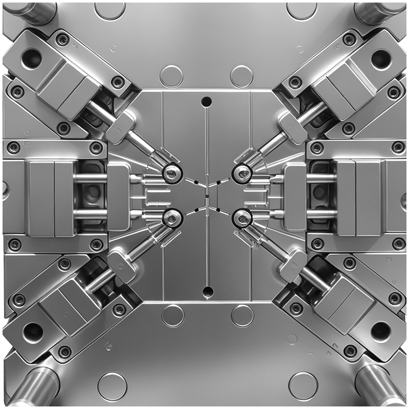 |
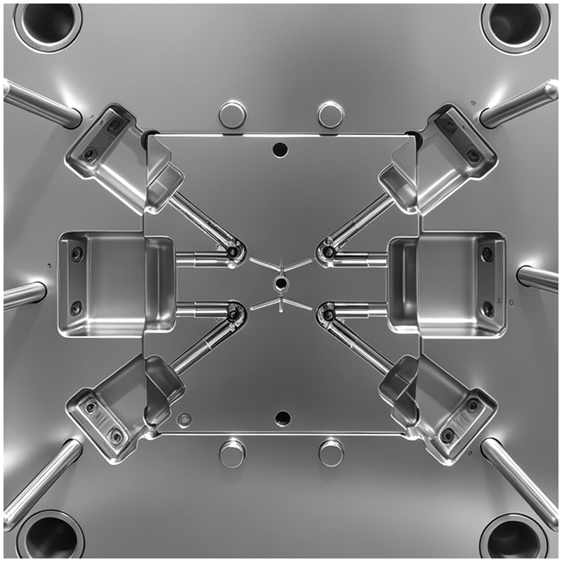
The typical structure of a three-way connector involves three mutually perpendicular hollow branches connecting to a main body. This geometry creates an extremely complex parting line and requires 3 long-distance sliders for core pulling.
Motion Interference: The three core-pulling axes meet at a central point. The slider strokes are long, making motion interference highly likely if the mold opening sequence is not strictly calculated.
Core Pin Deflection: The inner cores are long and thin. Under the high pressure of plastic injection, these slender cores can easily bend, causing eccentric inner holes and uneven wall thickness.
Parting Line Steps: With multiple sliders interlocking, even a 0.005mm mismatch can cause noticeable flash and parting line steps, ruining both the aesthetics and the sealing capability.
When the melt flows from the gate into the three branches, a large volume of air gets trapped right at the central intersection.
Burn Marks & Bubbles: Transparent resins like medical-grade PC, COC, or PPSU are zero-tolerant to defects. Trapped air causes localized overheating, leading to black burn marks, bubbles, and weakened knit lines.
Venting Blind Spots: Conventional venting slots cannot be opened at the intersecting dead corners. Engineers must rely on precise shallow venting (≤0.01mm) at the ends of the branches combined with vacuum-assisted venting.
Choosing the right gate location for this specific plastic mold is a balancing act:
Side Gate: Leads to uneven flow, where short shots and visible weld lines become inevitable.
Top Hot Runner Center Gate: The melt travels down and then turns 90 degrees into the side branches. This sharp turn creates a stagnation zone and shear overheating, causing the transparent material to yellow.
The Solution: Leading oem plastic manufacturing specialists use a valve-gate hot runner system with sequential filling. This controls the melt to arrive at the intersection simultaneously, neutralizing the weld lines.
To guarantee a leak-free connection, the concentricity between the core pin and the cavity must be controlled within 0.01mm. To achieve this level of accurate molding, the plastic mould tooling must feature:
Reinforced back-end supports and precision guide bushings for the core pins.
Straight-through internal water cooling channels inside the slender core pins to maintain thermal stability.
Cooling dictates the optical clarity and dimensional stability of the molding process.
Core Cooling: Without internal cooling in the core pins, localized hotspots will cause uneven shrinkage. The branches will warp or tilt inward/outward, making automated assembly impossible.
Conformal Cooling: The outer cavity must utilize 3D-printed conformal cooling channels to ensure a uniform cooling rate across the entire three-way shell, reducing internal stress that causes cracking under polarized light.
Flash vs. Venting: The venting depth at the branch ends must be strictly limited to ≤0.01mm. This allows gas to escape rapidly without creating any micro-flash.
Sequential Filling: Because external venting is impossible at the central cross-section, engineers use slower injection speeds and sequential valve gating to "push" the air smoothly to the ends.
Mirror Finish: Both the cavity and core pins require a mirror polish. Any micro-scratches will affect fluid dynamics and create stress concentration points.
Zero Step Tolerances: The alignment(step mismatch) between insert blocks must be <0.003mm. Any visible step on a transparent medical connector results in an immediate quality reject.
 EN
EN



 Hot News